 |
 |
 |
 |
Pre-compliant EMC test equipment and accessories
Tekbox is a supplier of affordable test equipment and accessories for pre-compliant EMI/EMC testing including Near Field Probe Sets, Antenna’s, Current Probes, Pre-amplifier and driver amplifiers, Open TEM cells, LISN’s, EMC software etc. The Tekbox products fit well with the Rigol DSA800, RSA3000(N) and RSA5000(N) series spectrum analyzers for pre-compliant EMC measurements.
 |
 |
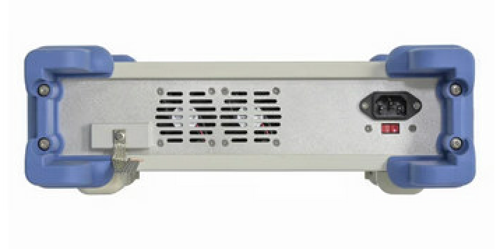 |
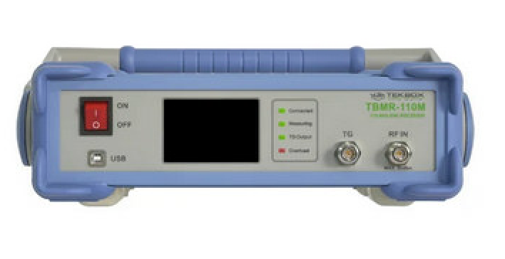
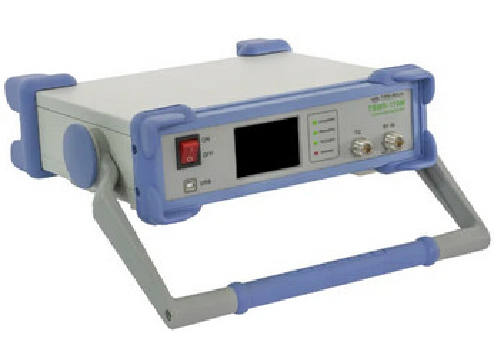
TBMR-110M EMI-ANALYZER DC-110 MHz
International EMC Standards require various spectrum measurement methods and equipment to ensure that the EUT´s electromagnetic emissions do not exceed the specified limits. The TBMR-110M EMI Analyzer is designed to carry out conducted emission measurements. Its affordability and versatility make it a perfect tool for engineers doing pre-compliance measurements during the development process. Its ease of use also enables importers of electronic items to periodically assess if their suppliers supply consistent quality in terms of EMC compliance, without having to outsource it to test laboratories. High accuracy, versatility and high-speed measurements are only a few of the many features.
Specifications
EMI Analyzer DC-110 MHz (Measurement Receiver’
- – 162 dBm/Hz noise floor down to 1 kHz
- 7-band hardware pre-selector filter bank
- 30 dBm maximum input power
- CISPR-16, ANSI and MIL-STD compliant detectors
- Peak, Quasi-Peak, Average, CISPR-Average, RMS and CISPR-RMS detectors working in parallel.
- Sweep, STFFT and direct parallel resolution bandwidth setting (-3 dB and -6dB)
- Numerous predefined Standards, ready to load and use
- Pre-measurement with selective Peak measurement
- Direct fast compliant STFFT measurement
- Many pre-defined transducers, antenna factors and various other compensation files
- Many data manipulation, display and documentation features
- Direct control from EMCView or standalone operation
- Quick load of predefined setups
Spectrum Analyzer
- True DC – 110 MHz measurement range
- Tracking Generator
- 0.1 Hz to 3.5 MHz arbitrary RBW and VBW setting
- Zero Span operation with time domain triggering
- Linear, log amplitude and frequency display
- Sweep, STFFT and direct parallel resolution bandwidth setting
- Parallel RMS, Pos./Neg. peak and average detector
- Trace Memory option, normalization
- Equation based trace display
- Peak hold
- Noise marker, max and band power display
- Quick load of predefined setups
Tracking Analyzer DC – 110 MHz
- Linear and logarithmic sweep
- -50 dBm to 0 dBm adjustable TG power
- 120 dB dynamic range
- Use of power correction file and level correction file
- Quick load of predefined setups.
Oscilloscope 250 MS/s, DC – 110 MHz
- 1 ns/DIV to 1 s/DIV horizontal resolution
- Interpolated sampling up to 4 GS/s
- Real-time Sampling up to 250 MS/s, 14 Bit
- Up to 16 MS sampling size
- Various Trigger options
- Vertical CIC Filter option for noise reduction
- Many automatic measurement features
Demodulator
- Direct demodulation into the PC sound system
- FM, AM and SSB demodulator
- Adjustable bandwidth, center frequency and demodulator parameters
- Automatic demodulation parameter measurements
IQ Stream Generator
- GNU-Radio data source
- Directly stream floating point I and Q data into file or network
- Adjustable center frequency and bandwidth
Remote Control
- Direct remote control of the EMI Analyzer over network
- Text based protocol
- EMCview compatible
![]() User Manual EMCview or EMC pre-compliance testing
User Manual EMCview or EMC pre-compliance testing
![]() Why do_I_need_a_software_for_EMC_Measurements
Why do_I_need_a_software_for_EMC_Measurements
![]() AN Spectrum Analyzers for EMC testing
AN Spectrum Analyzers for EMC testing
![]() AN Using RF current probes with EMCview
AN Using RF current probes with EMCview
![]() AN Using EMCview to extrapolate RF Current Probe Measurements to to electric field strength
AN Using EMCview to extrapolate RF Current Probe Measurements to to electric field strength
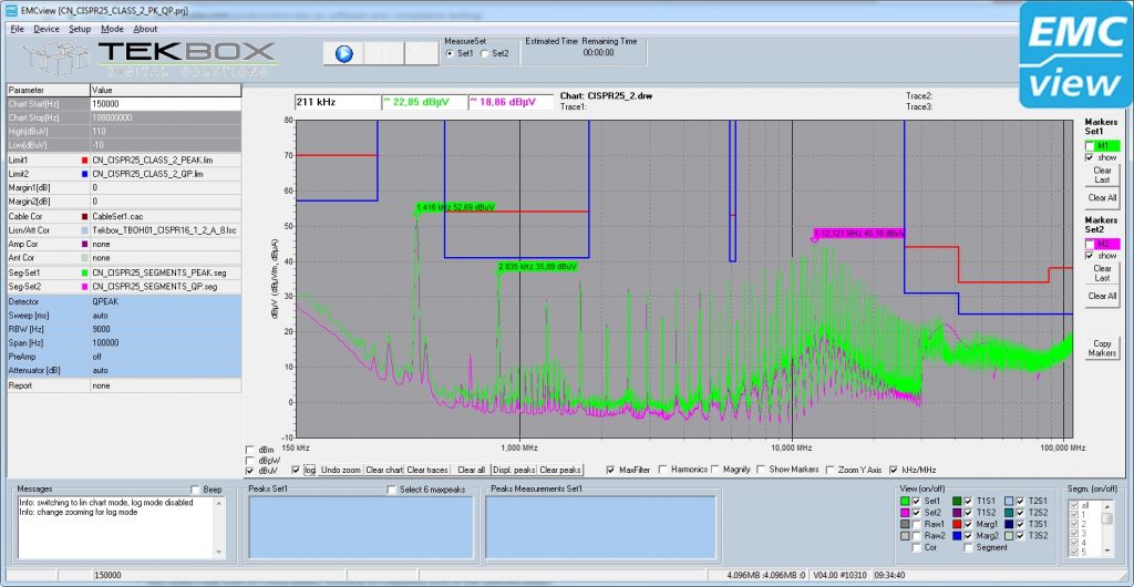
EMCview PC software for EMC pre-compliance testing
The Tekbox EMC compliance software EMCview for PCs is a user-friendly EMC pre-compliance testing of radiated and conducted emissions. It is a perfect complement for automated testing using our LISNs, RF current probes, measurement antennas and TEM Cells.
A built-in amplitude correction enables correction and conversion coefficients for cables, amplifiers, attenuators, LISNs, TEM cells, antennas, RF current probes, filters and any other component in the signal chain.
There is no need for a time-consuming setup. The SW is ready for measurements straight after installation. All emission related standards and a few automotive manufacturer standards are pre-configured in corresponding project files. The project files take care of all necessary settings to conduct standard compliant measurements. Besides using pre-configured projects, the user can easily create his own projects using a built in editor or any simple text editor.
The graph supports two complete measurement runs such as for example Average / Quasi-Peak or Peak / Quasi Peak and in addition a fast Quasi-Peak scan of critical peaks. Graphs can be saved and overlayed with newer measurements to track and document design modifications.
Furthermore, EMCview together with our GPS receiver can be used to carry out RF-coverage measurements. An export feature creates KML files which links the result to google maps.
Immunity testing is supported with dedicated menus, controlling the tracking generator of the spectrum analyzer.
EMCview PRO, offers real-time measurement support for spectrum analyzers with real-time capability. Furthermore, EMCview PRO offers advanced conducted immunity testing features for spectrum analyzers with tracking generators. The customer can select between a standard EMCview license or EMCview PRO. Users with a standard EMCview license have the option to upgrade to EMCview Pro.
EMCview Standard Features
- numerous pre-configured project files for all relevant EMC standards
- Graph supports two complete measurement runs, same as in test house; simultaneous measurement with two detectors available for a few analyzers
- fast Quasi-Peak scan of critical peaks, immune to frequency drift of the selected peaks
- Fast pre-scan
- configurable limit lines and segment files
- configurable correction files for cables, LISN, amplifiers, antennas, current probes, etc.
- configurable margins for the identification and selection of critical peaks
- supports import and overlaying of reference measurements for comparison purpose
- linear or logarithmic frequency axis
- Harmonic markers
- automatic creation of test reports
- many import/export-functions
- graphs can be saved as charts containing meta-data, graphs can be loaded together with the corresponding measurement configuration
- RF coverage measurements
- tracking generator control for immunity testing using TEM cells
- many post-processing features
- useful calculators
EMCview Pro Features
- Everything the standard version offers
- Immunity testing using CDNs or BCI probes
- Rapid measurement, supporting real time bandwidth capability of Siglent SSA3000X-R series and Rigol RSA series
Open (G)TEM Cells |
||
 |
 |
 |
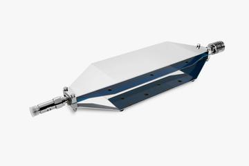
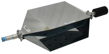
| TBTC0 Open TEM Cell, 28 mm Septum Frequency Range emission : 9 kHz – 3.15GHz Frequency Range immunity : 9 kHz – 6 Ghz Max Input Power : 100 Watt* Usable area under septum : 190 x 70 mm Septum Heigth : 28 mm Outer Dimensions : 390 x 100 x 62 mm *requires 100 Watt attenuator |
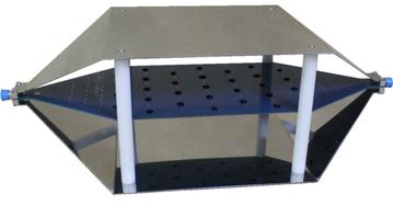
TBTC1 Open TEM Cell, 50 mm Septum Frequency Range emission : 9 kHz – 2.1 GHz Frequency Range immunity : 9 kHz – 6 GHz Max Input Power : 500 Watt* Usable area under septum : 190 × 130 mm Septum Heigth : 50 mm Outer Dimensions : 390 x 200 × 108 mm *requires 500 Watt attenuator |
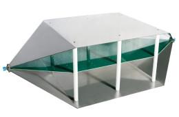
TBTC2 Open TEM Cell, 100 mm Septum Frequency Range emission : 9 kHz – 1.2 GHz Frequency Range immunity : 9 kHz – 6 GHz Max Input Power : 500 Watt* Usable area under septum : 230 x 280 mm Septum Heigth : 100 mm Outer Dimensions : 636 x 300 × 205 mm *requires 500 Watt attenuator |
 |
 |
|
| TBTC3 Open TEM Cell, 150 mm Septum Frequency Range emission : 9 kHz – 6 GHz Frequency Range immunity : 9 kHz – 700 MHz Max Input Power : 500 Watt* Usable area under septum : 360 x 480 mm Septum Heigth : 150 mm Outer Dimensions : 1038 × 501 x 305 mm *requires 500 Watt attenuator |
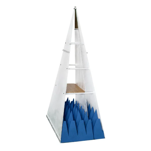
New TBGTC1 Open GTEM Cell, 250 mm Septum Frequency Range emission : 9 kHz – 6 GHz Frequency Range immunity : 9 kHz – 6 GHz Max Input Power : 600 Watt Usable area under septum :200 x 200 x 150 mm Septum Heigth : 250 mm at EUT-board Outer Dimensions : 1452 x 780 x 520 mm |
|
Shielded Tents & Shielded Bags |
||
 |
 |
 |
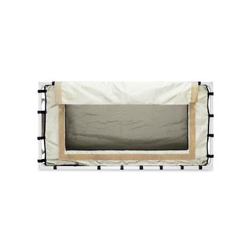
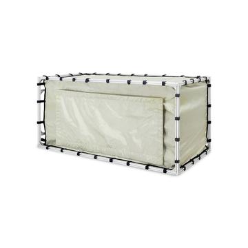
| TBST120/60/60/2-B Shielded Tent 120 cm x 60 cm x 60 cm Filter Panel with 10 A AC Mains and 2 x 10 A DC Filters, 3 x N and 1 x BNC, ~ 50-70 dB shielding from DC to 6 GHz Fits up to TBTC3 Open TEM cell |
TBST86/49/45/1-B Shielded Tent 86 x 49 x 45 cm Filter Panel with 10 A AC Mains and 2 x 10 A DC Filters,3 x N and 1 x BNC, ~ 50-50 dB shielding DC to 6 GHz Fits up to TBTC2 Open TEM cell |
TBST86/49/45/2-B Shielded Tent 86 x 49 x 45 cm Filter Panel with 2 x 10 A DC Filters, 3 x N and 1 x BNC, ~ 50-70 dB shielding DC to 6 GHz Fits up to TBTC2 Open TEM cell |
 |
 |
|
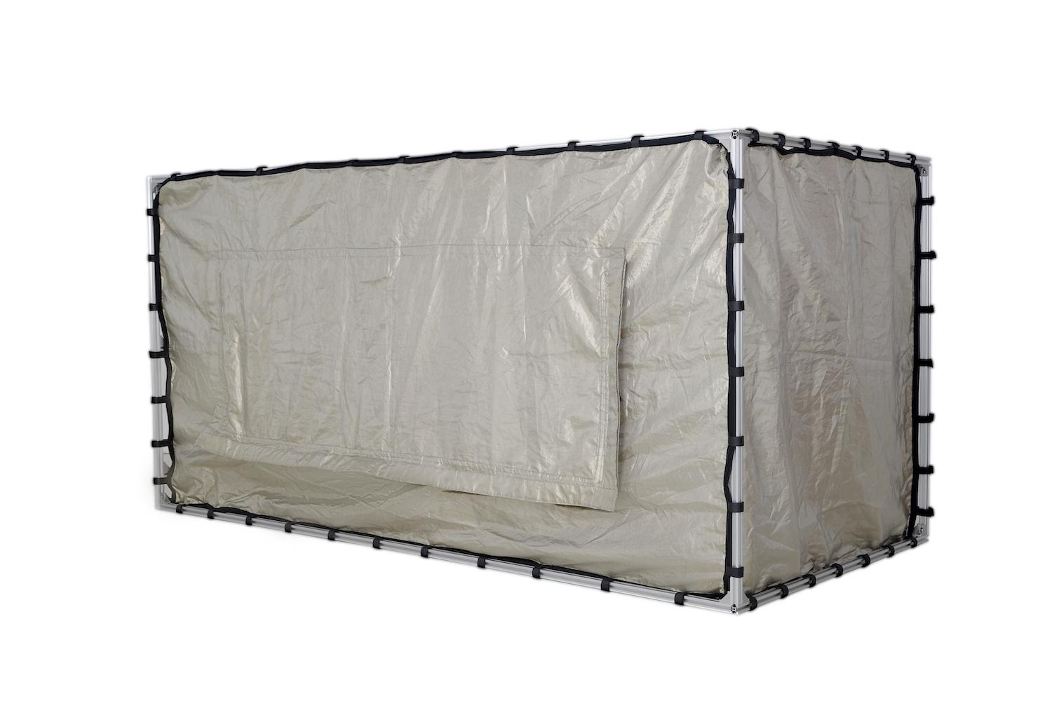
| New TBST200/100/100 Shielded Tent 204 x 100x 104 cm Filter Panel with 2 x 10 A DC Filters, 3 x N and 1 x BNC,~ 50-70 dB shielding DC to 6 GHz ~30 dB DC-10 MHz, ~50 dB 10MHz to 6 GHz Fits all Tekbox LISNs or TEM-cells |
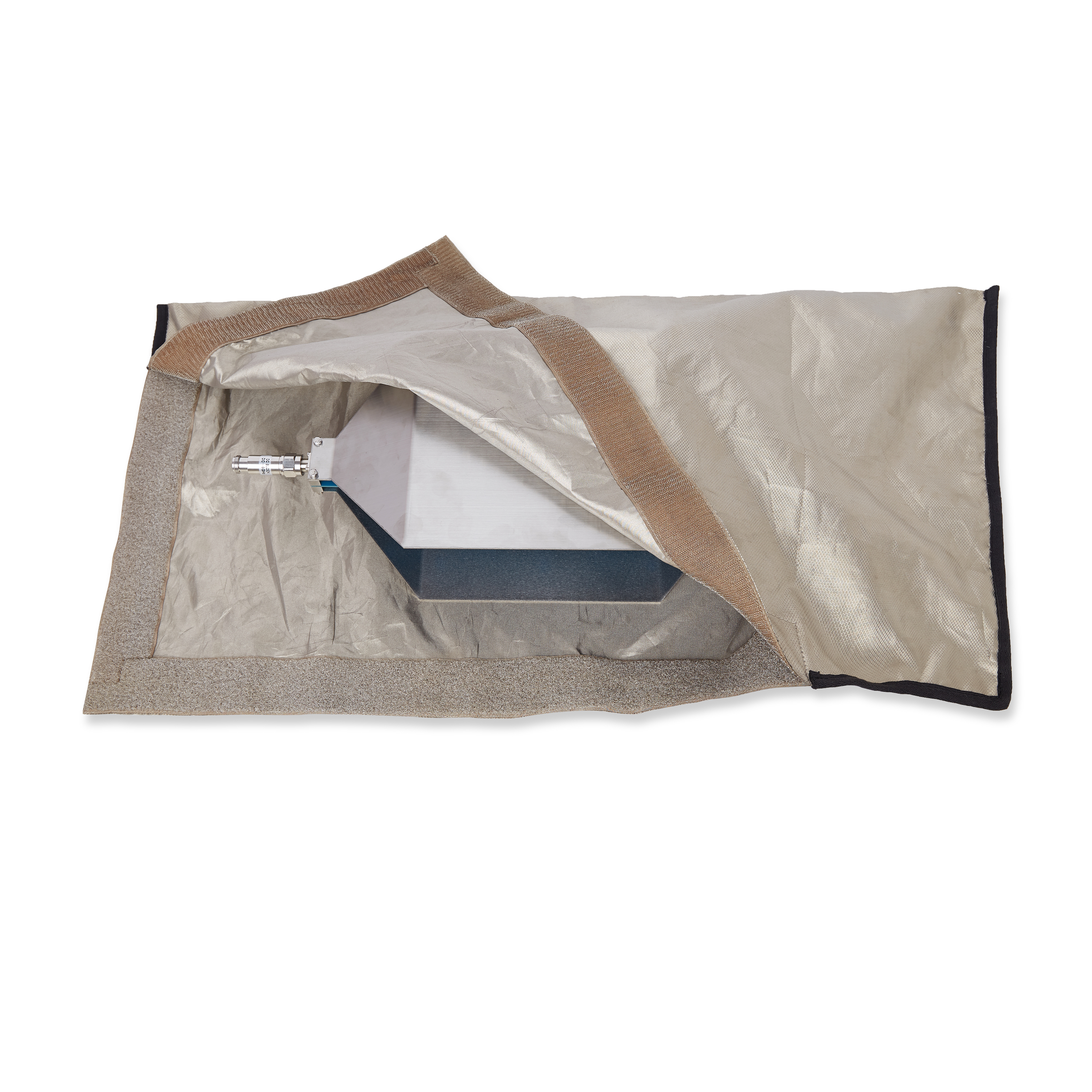
New TBSB-105/60 & TBSB-70/40 Shielded Bag 105 x 60 cm or 70 x 40 cm ~ 50 dB shielding in the range DC to 2 GHz TBSB-105/60 Fits up to TBTC2 TBST=B-70/40 Fits upo to TBTC1 |
|
 |
 |
 |
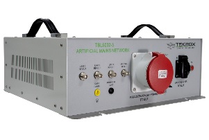
| New TBL5032-3-EU 50 Ω ║ (50 µH + 5 Ω), 3 Phase and 1 Phase Separate RF outputs for each phase and neutral 9 kHz – 30 MHz, 450V/260V, 32 A according to:
|
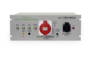
TBL5016-3 50 Ω ║ (50 µH + 5 Ω), 3 Phase and 1 Phase Separate RF outputs for each phase and neutral 9 kHz – 30 MHz, 450V/260V, 16 A according to:
|
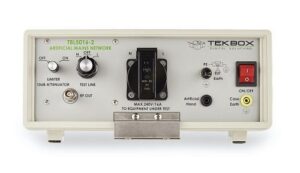
TBL5016-2 50 Ω ║ (50 µH + 5 Ω) LISN, 1 Phase 9 kHz – 30 MHz, 240 Vac, 16 A according to:
|
 |
 |
 |
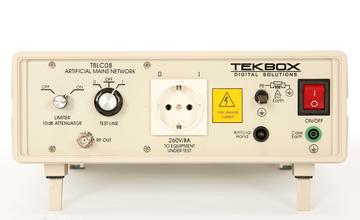
| TBLC08 50 Ω ║ (50 µH + 5 Ω) LISN, 1 Phase 9 kHz – 30 MHz, 240 Vac, 8 A according to :
|
TBL5016-1 50 Ω ║ (50 µH + 5 Ω) or 50Ω ║50µH LISN, 1 Path 9 kHz – 100 MHz, 250V AC/DC; (50/60 Hz), 16 A According to:
|
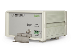
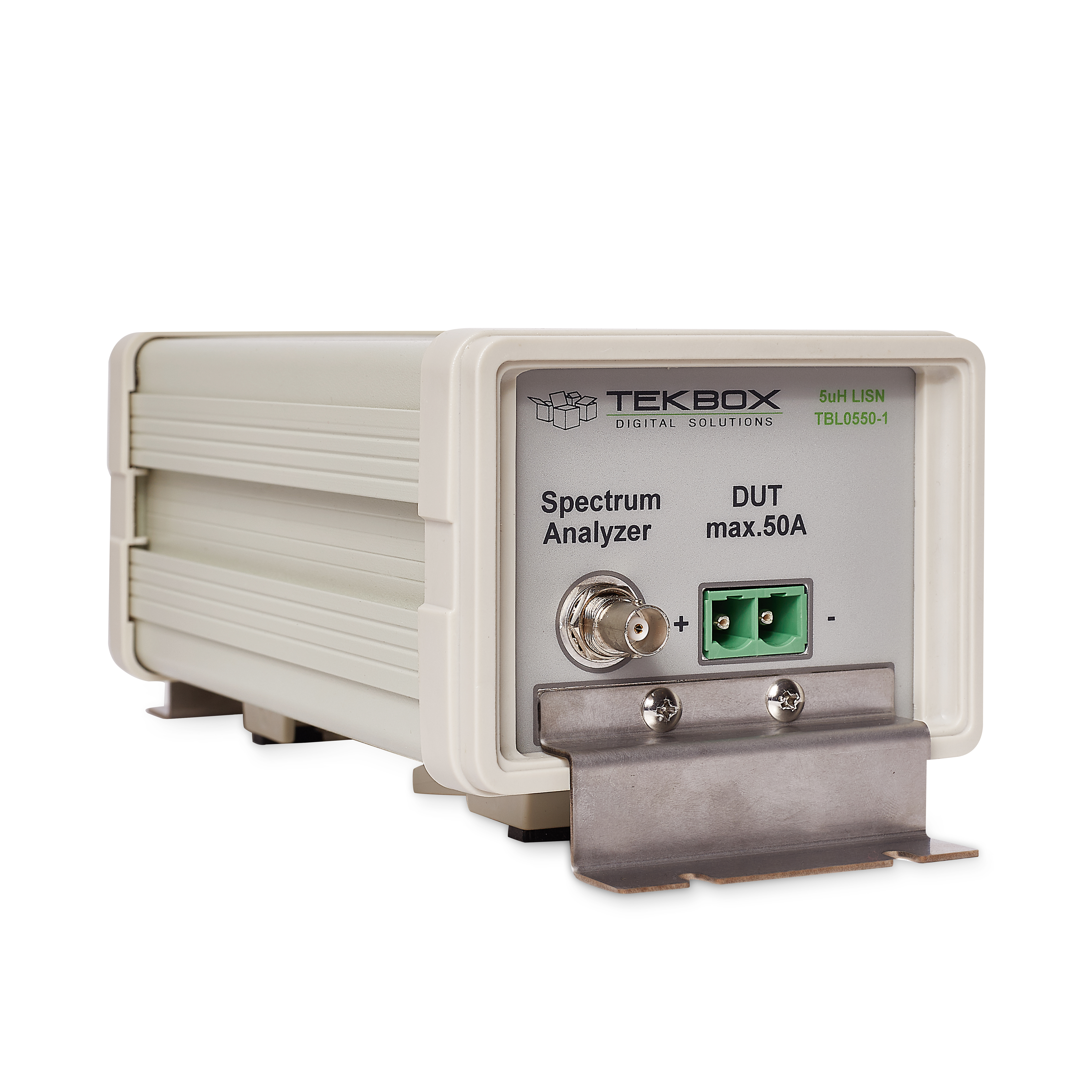
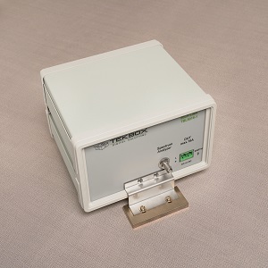
TBL0550-1 5 μH DC LISN, 1 Path 150 kHz to 150 MHz, 0/60 Vdc, 50 A According to :
|
 |
 |
 |
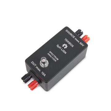
| TBOH01 5µH DC LISN, 1 Path 150 kHz – 110 MHz, 0-60 Vdc, 10 A According to :
|
TBGP Roll Up Ground Plane Dimensions 250 cm x 140 cm Polyester 45% + Silver 55% conductive fabric, fleece 4 Nickel Plated Contact Blocks, each 95 mm x 40 mm x 8 mm |
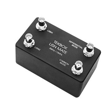
TBLM1_LISN |
|
|
||
 |
|
|
|
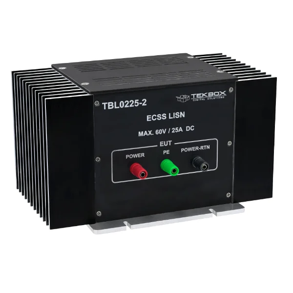
New TBL0225-2
|
|
|
|
 |
 |
 |
| TBPS01 EMC Near Field Probe Set |
TBPS01-TBWA2/20dB EMC Near-field Probe Set + 20 dB Wideband Amplifier in wooden box |
TBPS01-TBWA2/40dB EMC Near-field Probe Set + 40 dB Wideband Amplifier in wooden box |
 |
 |
 |
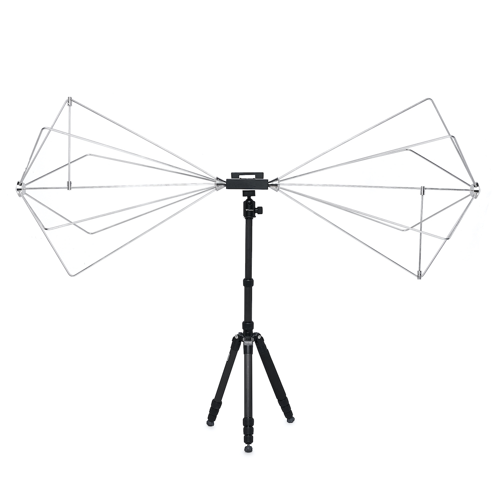
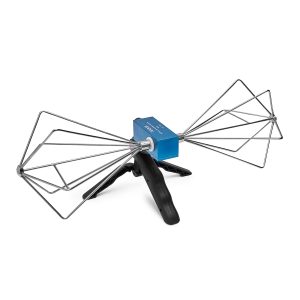
| TBMA1 Wideband Biconical Measurement Antenna 30 MHz – 1000 MHz Mini Tripo, Hand Grip Included Delivered in Wooden Box Ideal for radiated noise EMC pre-compliance testing |
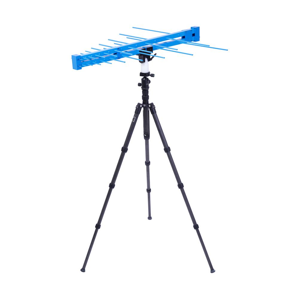
TBMA2 Biconical Antenna for Radiated Emission and Immunity 30 MHz – 300 MHz 100 Watt Max Continuous Input Power 1:4 Balun Excellent Antenna Factor Excellent for in house pre-compliance testing |
TBMA3 |
 |
 |
 |
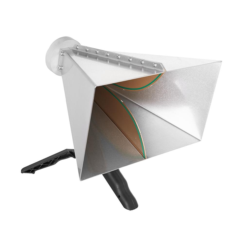
| TBMA4 Double Ridged Horn Antenna 1 – 8 GHz 100 Watt Max Continuous Input Power Isotropic gain: 6 … 14 dBi Antenna factor: 24 … 43 dB/m |
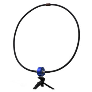
TBMA6-P Passive Loop Antenna 9 kHZ – 30 MHz According to CISPR16 60 cm Loop (40 optional available) |
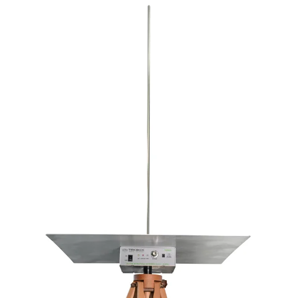
New TBMA5 Active Monopole Antenna 9 kHz – 30 MHz CISPR 16, CISPR 25 or MIL-STD-461G 104 cm Monopole |
 |
 |
|
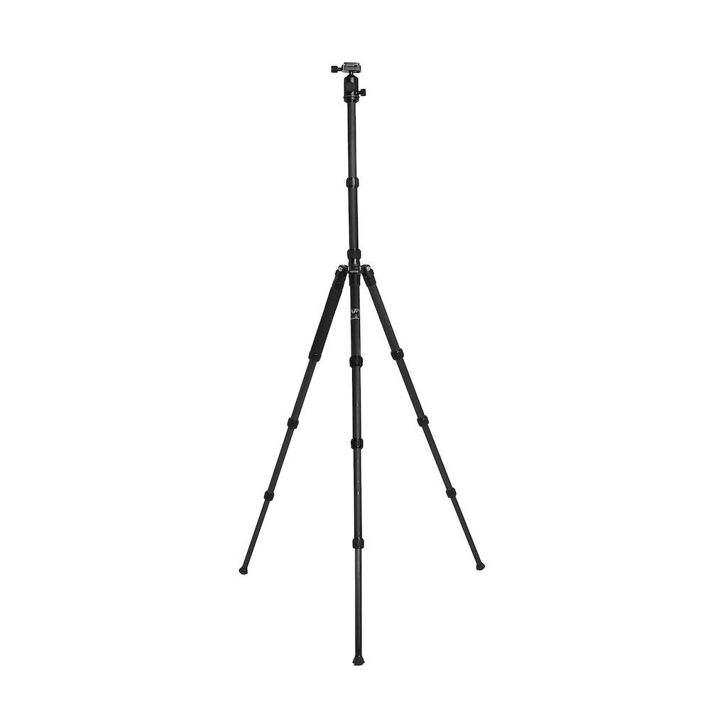
| TBTP1 1490mm Tripod suitable for all Tekbox Antennas Carbon Fiber Highest Height: 1490mm Net Weight: 1.37kg Load-bearing: 6 kg |
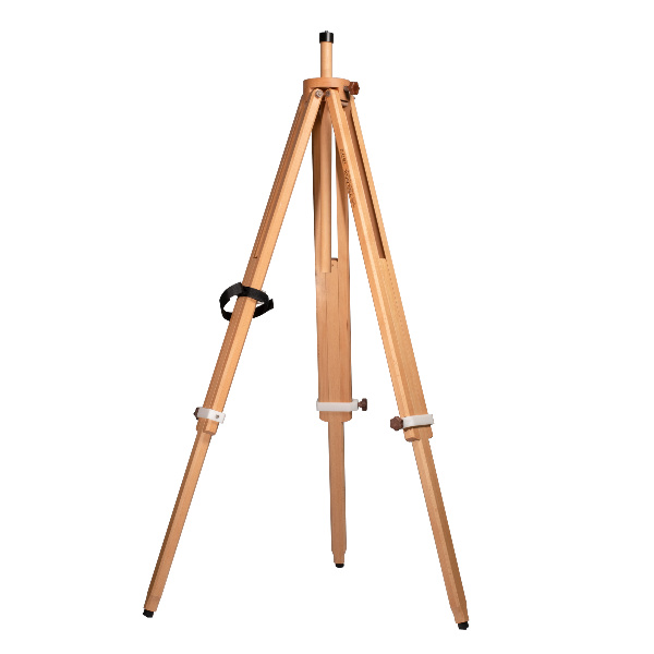
TBTP3 Tripod, made out of beech wood Height range: 800 mm – 1800 mm Net Weight: 3.4 kg Load-bearing: 8 kg |
|
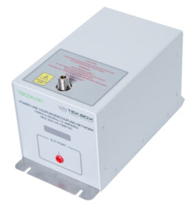
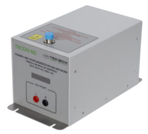
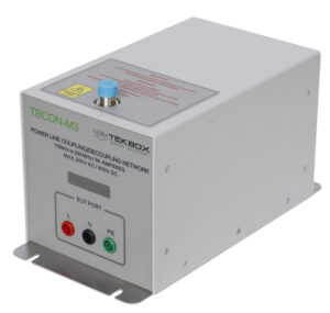
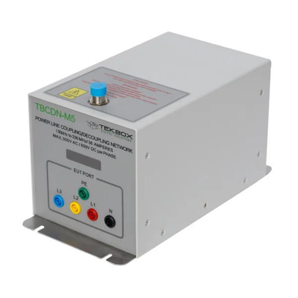
The TBCDN-MX are a Coupling Decoupling Networks for conducted immunity testing according to IEC 61000-4-6. The TBCDN-MX are compliant with IEC 61000-4-6 Annex D2. It is designed to inject common mode disturbance signals in the frequency range from 150 kHz to 230 MHz into unscreened AC and DC power supply lines. |
 |
 |
 |
| TBCDN M1 Coupling Decoupling Network M1
|
TBCDN M2 Coupling Decoupling Network M2
|
TBCDN M3 Coupling Decoupling Network M3
|
 |
 |
 |
| TBCDN_M5 Coupling Decoupling Network M5
|
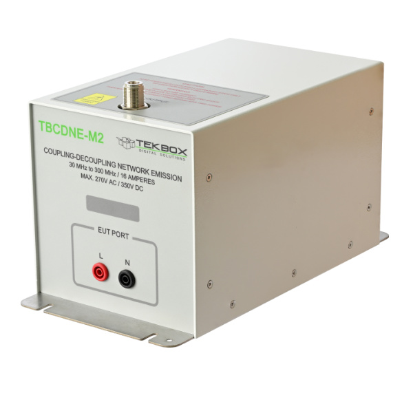
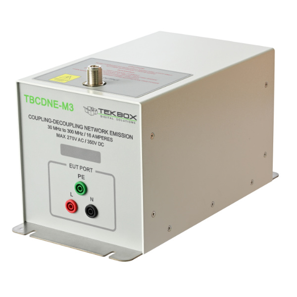
New TBCDNE_M3 Coupling Decoupling Network Emission
|
New TBCDNE_M3 Coupling Decoupling Network Emission
|
 |
 |
 |
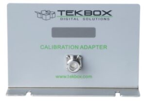
| TBCDN_Mx Calibration adapters for M1 ..M5 CDN’s
|
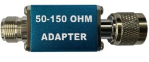
TBCDN-50-150 |
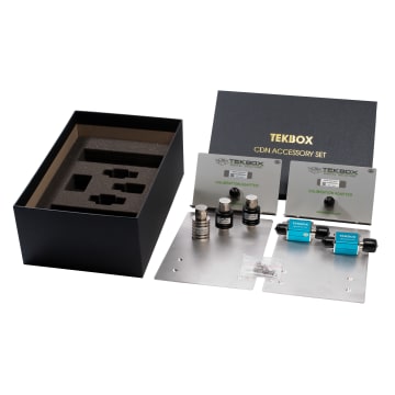
TBCDN_AS_Mx Accessory Set includes everything needed for a CDN calibration setup2 x Aluminium groundplanes2 x TBCDN-50-150 50Ω to 150Ω N-male to N-female adapter 2 x TBCDN-Mx-AP Adapter panel with shorting bar for Mx coupling decoupling network, N-Female to 4mm Banana plug 1 x 6dB Attenuator, 10W, 3GHz, N-connector 1 x 3dB Attenuator, 10W, 3GHz, N-connector 1 x 50Ω Termination, 10W, 6GHz, N-connector |
| Modulated Driver Amplifiers | ||
 |
 |
 |
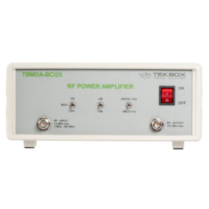
| New TBMDA-BCI25 Modulated Wideband Power Amplifier 1 MHZ – 400 MHz, Small signal gain: 47 dB typ. P1dB up 45.6 dBm CW, 1 kHz 80% AM, 1 kHz 50% pulse, 217 Hz 12.5% 110 – 240 Vac |
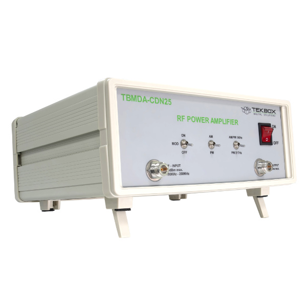
New TBMDA-CDN25 Modulated Wideband Power Amplifier 100 kHz – 250 MHz, Small signal gain: 47 dB typ. P1dB up to 25 Watt CW, 1 kHz 80% AM, 1 kHz 50% pulse, 217 Hz 12.5% 110 – 240 Vac |
New TBMDA5 Modulated Power Amplifier 150 kHz –400 MHz, Small Signal Gain dB typ, P1dB 2.5 Watt from 150 kHz – 400 MHz CW, 1 kHz 80% AM, 1 kHz 50% pulse, 217 Hz 12.5% 110 – 240 Vac |
 |
 |
 |
| New TBMDA4B Modulated Power Amplifier 100 kHz – 75 MHz, Gain up to 49.9 dB, Up to +37 dBm P1dB (5 Watt) CW, 1 kHz 80% AM, 1 kHz 50% pulse, 217 Hz 12.5% 110 – 240 Vac |
New TBMDA3B Modulated Power Amplifier 10 MHz – 1 GHz, Gain 42 dB typ, Up to +40.2 dBm P1dB (10 Watt) CW, 1 kHz 80% AM, 1 kHz 50% pulse, 217 Hz 12.5% 110 – 240 Vac |
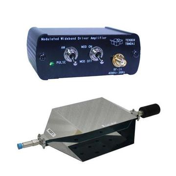
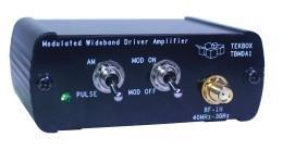
TBMDA1 Modulated Wideband Driver Amplifier 25 MHz-3 GHz, gain up to 25 dB, 22 dBm P1dB CW, 1 kHz 80% AM, 1 kHz 50% pulse, 217 Hz 12.5% |
 |
||
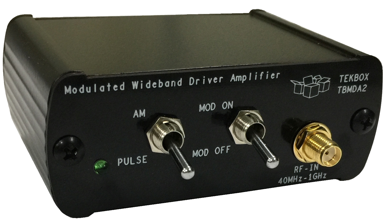
| TBMDA2 Modulated Wideband Driver Amplifier 10 MHz-1.5 GHz, Gain up to 46.7 dB, up to +27 dBm P1dB |
||
Probe, Driver and High Dymanic Range Pre-amplifiers |
||
 |
 |
 |
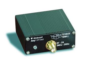
| TBWA2/20dB or /40dB Wideband (EMC Probe) Amplifier 1.5 MHz – 6 GHz, Gain 20 or 40 dB, NF 4.5 dB |
TBDA1/14dB or /28dB Wideband Driver Amplifier 25 MHz – 3 GHz, 14 dB or 28 dB gain, +22 dBm P1dB |
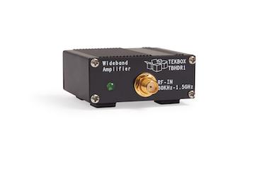
TBHDR1 High Dynamic Range EMC Pre-Amplifier 30 kHz – 1.5 GHz (6 GHz) Gain up to 24 dB, 19 dBm typ P 1dB, 2.7 dB NF |
Linear Wideband Power Amplifier |
||
 |
||
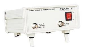
| TBLPA1 Linear Wideband Power Amplifier 10 MHz – 1 GHz, Up to 1 Watt |
||
Injection Transformers |
||
 |
 |
|
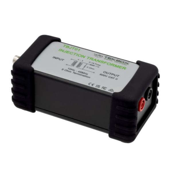
| New TBJT01 wideband injection transformer 10 Hz to 45 MHz |
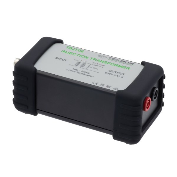
New TBJT02 wideband injection transformer 1 Hz to 7 MHz |
|
Bulk Current Injection Probes |
||
 |
 |
 |
| New TBBCI1-200K280 Bulk Current Injection probe for IEC / EN 61000-4-6 10 kHz to 300 MHz Power rating: capable of injecting level 1, 2, 3 and stress level X up to 30V, 150 Ohm test set-up according to IEC/EN 61000-4-6 |
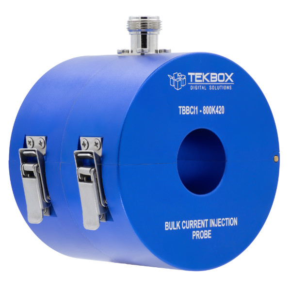
New TBBCI1-800K420 Bulk Current Injection probe for ISO 11452-4; IEC / EN 61000-4-6 10 kHz to 500 MHz Power rating: capable of injecting severity levels I, II, III, IV according to ISO 11452 and customer specified level V up to 350 mA |
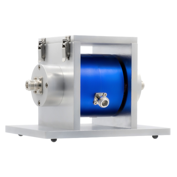
New TBBCI1 Bulk Current Injection Probe Calibration Fixture 50 Ω termination Optional TBCDN–50–150 50 Ohm to 150 Ohm adapter for 300 Ohm loop calibrations |
RF pulse current monitoring probe |
||
 |
 |
|
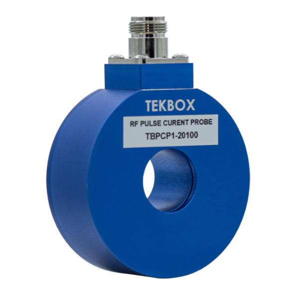
| New TBPCP1-20100 20 Hz to 100 MHz (-3 dB) 1 Hz to 200 MHz (Characterized) Transfer impedance into 50 Ohm -20 dB Ohm; 0.1 V/A TransferTransfer impedance into high Z: 0.2 V/A Up to 3000 A Puls
|
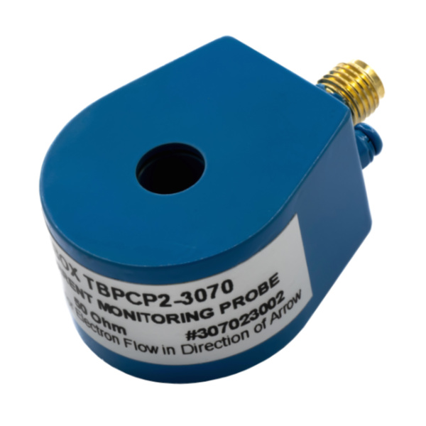
New TBPCP2-3070 30 Hz to 70 MHz (-3dB) 1 Hz to 200 MHz (Characterized) Transfer impedance into 50 Ohm -26 dB Ohm; 0.05 VA Transfer impedance into high Z: 0.1 V/A Up to 400 A Pulse |
|
RF Surface Current Monitoring Probes |
||
 |
 |
|
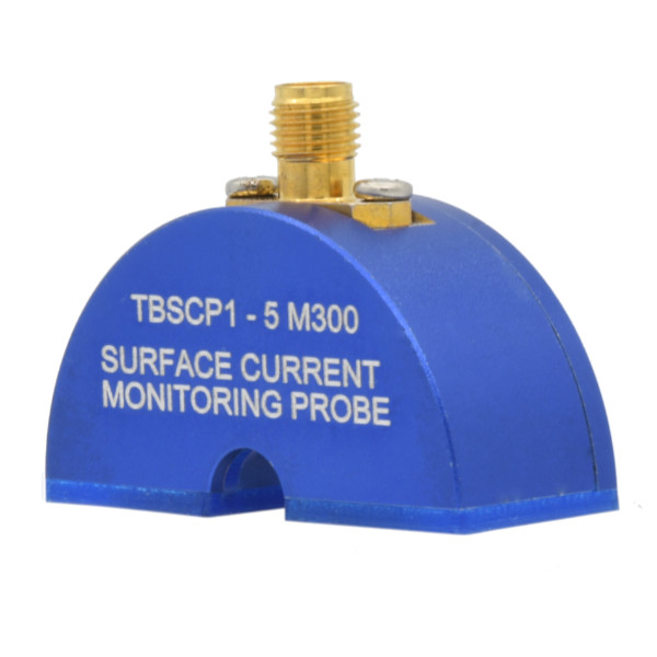
| New TBSCP1_5M300 RF surface current monitoring probe 30 kHz to 400 MHz |
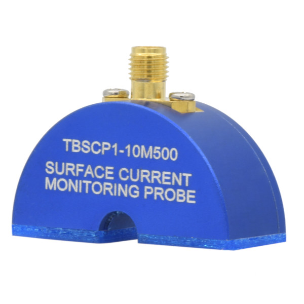
New TBSCP1_10M500 RF surface current monitoring probe 30 kHz to 600 MHz |
|
Coaxial RF Current Monitor Probes |
||
 |
 |
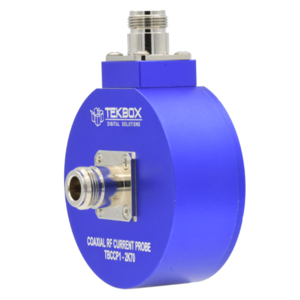 |
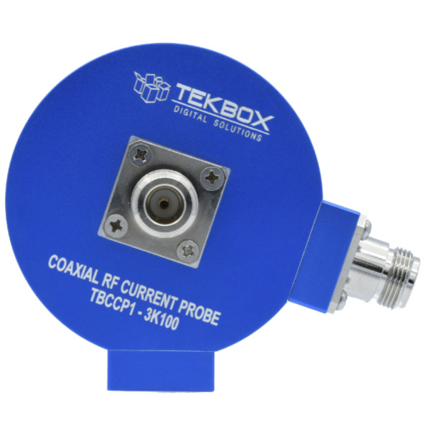
| new TBCCP1_3K100 coaxial RF current monitoring probe 10 Hz to 100 MHz |
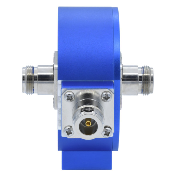
New TBCCP1_400K600 coaxial RF current monitoring probe 10 Hz to 600 MHz |
New TBCCP1_2K70 coaxial RF current monitoring probe 10 Hz to 100 MHz |
Snap On RF Current Monitor Probe 32 mm |
||
 |
 |
 |
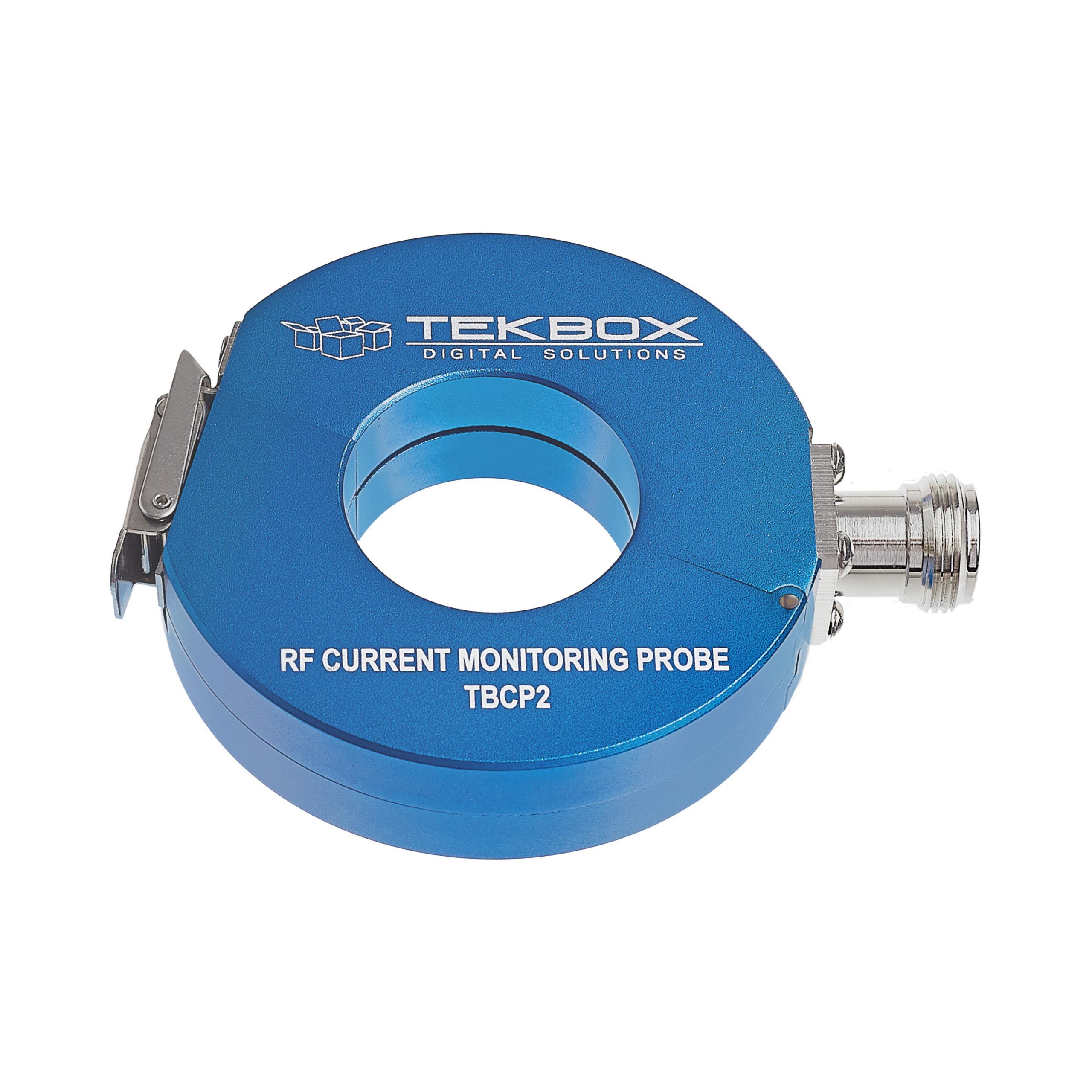
| TBCP2-250 Snap On RF Current Monitor Probe 10 kHz – 250 MHz 32 mm Aperture |
TBCP2-500 Snap On RF Current Monitor Probe 10 kHz – 500 MHz 32 mm Aperture |
TBCP2-750 Snap On RF Current Monitor Probe 10 kHz – 750 MHz 32 mm Aperture |
 |
||
| TBCP2 30K400 RF Current Monitoring Probe 10 Hz to 500 MHz 32 mm Aperture higher sensitivity in the low frequency range |
||
RF Current Monitor Probes Fixed Aperture 17, 25 and 32 mm
|
||
 |
 |
 |
| TBCP4-250 RF Current Monitoring Probe 10 kHz – 250 MHz 32 mm fixed aperture |
TBCP4-500 RF Current Monitoring Probe 10 kHz – 500 MHz 32 mm Fixed aperture |
TBCP4-750 RF Current Monitoring Probe 10 kHz – 750 MHz 32 mm fixed aperture |
 |
 |
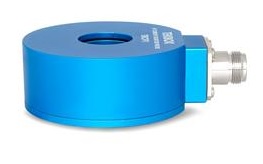 |
| TBCP3-1000 RF Current Monitoring Probe 30 kHz – 1 GHz 17 mm fixed aperture |
TBCPx-CAL Calibration Fixture RF Current Probe Calibration Fixtures For TBCP1 thru TPCP4 serie |
TBCP1-250 RF Current Monitoring Probe 30 kHz – 250 MHz 25 mm fixed aperture |
 |
 |
|
| TBCP1-200 RF Current Monitoring Probe 10 kHz – 200 MHz 25 mm fixed aperture |
TBCP1-500 RF Current Monitoring Probe 30 kHz – 500 MHz 25 mm Aperture |
|
 |
 |
 |
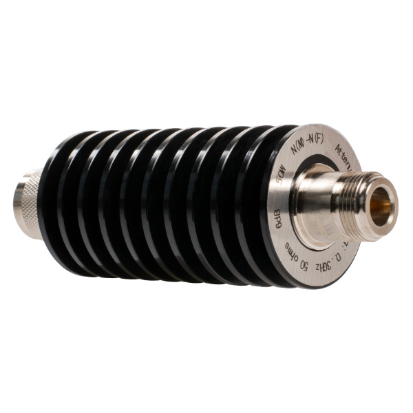
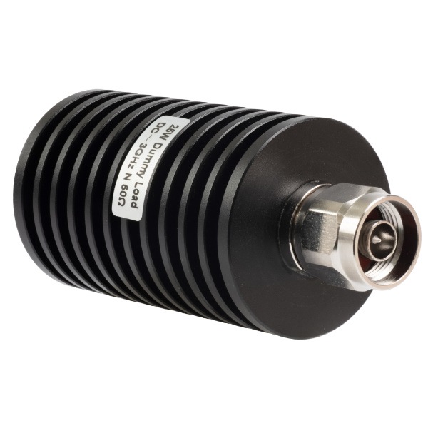
| New TBATT RF attenuators DC-3 GHz 10, 25, 50 or 100 Watt 3, 6, 10, 20, 30 dB N(m)/N(f) Connectors |
New TBTERR RF Terminations DC-1, 2, 3 0r 6 GHz 0.5, 3, 10, 24 Watt N(m) or BNC (m) |
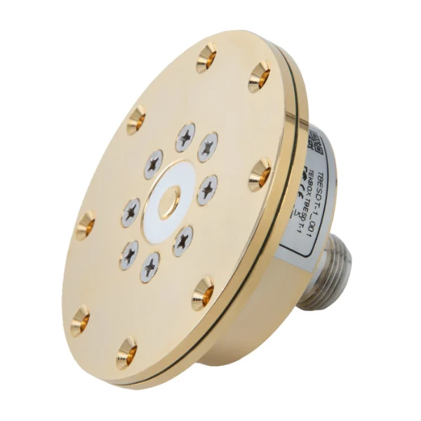
TBESDT1 ESD Target IEC 61000-4-2 Compliant Frequency Range : DC – 4 GHz Max. pulse amplitude: ± 30 kV Including 20 dB Attenuator |
 |
 |
 |
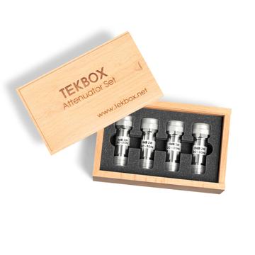
| TBAS1 N type RF Attenuator Set DC-3 GHz, 2 Watt, 3, 6, 10, 20 dB |
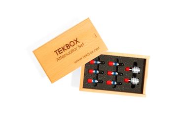
TBAS2 SMA type RF Attenuator / Termination Set DC-6 GHz, 1 Watt, 3, 6, 10, 15, 20, 30 dB & 2 pcs 50 Ohm terminations |
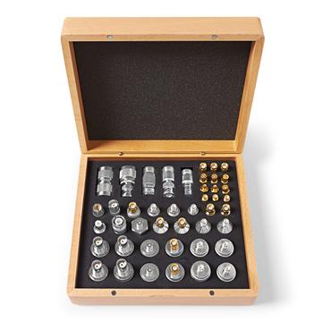
TBCAS1 Coaxial Adapter Set 44 pcs of most common coaxial adapters |
 |
 |
 |
| TBAS3 10 Watt RF Attenuator Set DC – 3 GHz, 10 Watt, 3, 6, 10, 20 dB |
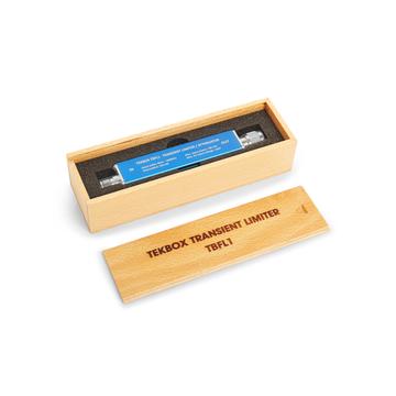
TBFL1 Transient Limiter 9 kHz – 600 MHz |
TBST120/60/60/2-B Shielded Tent 120 cm x 60 cm x 60 cm Filter Panel with 10 A AC Mains and 2 x 10 A DC Filters, 3 x N and 1 x BNC, ~ 50-70 dB shielding from DC to 6 GHz Fits up to TBTC3 Open TEM cell |
 |
 |
 |
| TBST86/49/45/1-B Shielded Tent 86 x 49 x 45 cm Filter Panel with 10 A AC Mains and 2 x 10 A DC Filters,3 x N and 1 x BNC, ~ 50-50 dB shielding DC to 6 GHz Fits up to TBTC2 Open TEM cell |
TBST86/49/45/2-B Shielded Tent 86 x 49 x 45 cm Filter Panel with 2 x 10 A DC Filters, 3 x N and 1 x BNC, ~ 50-70 dB shielding DC to 6 GHz Fits up to TBTC2 Open TEM cell |
New TBST200/100/100 Shielded Tent 204 x 100x 104 cm Filter Panel with 2 x 10 A DC Filters, 3 x N and 1 x BNC,~ 50-70 dB shielding DC to 6 GHz ~30 dB DC-10 MHz, ~50 dB 10MHz to 6 GHz Fits all Tekbox LISNs or TEM-cells |
 |
 |
 |
| New TBSB-105/60 & TBSB-70/40 Shielded Bag 105 x 60 cm or 70 x 40 cm ~ 50 dB shielding in the range DC to 2 GHz TBSB-105/60 Fits up to TBTC2 TBST=B-70/40 Fits upo to TBTC1 |
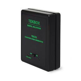
TBCG1 Radiating Comb Generator 100 MHz Base Frequency, 30 MHz -6 GHz |
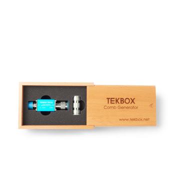
TBCG2 Comb Generator/Frequency Multiplier Input Frequency: 1 MHz – 350 MHz Comb spectrum: 1 MHz – 2.5 GHz |
 |
 |
 |
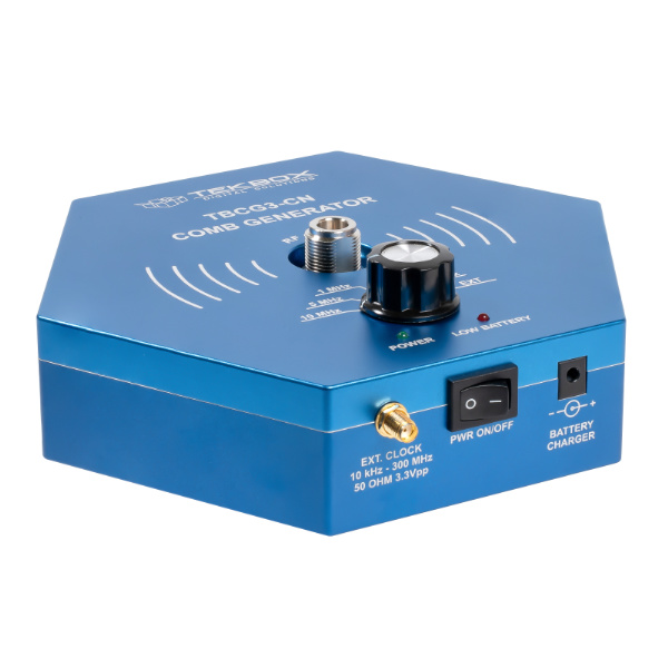
| New TBCG3-CN Comb Generator Conducted Noise Specified Bandwidth : 1.5 GHz Comb Frequencies : 100 kHz, 500 kHz, 1 MHz, 5 MHz, 10 MHz |
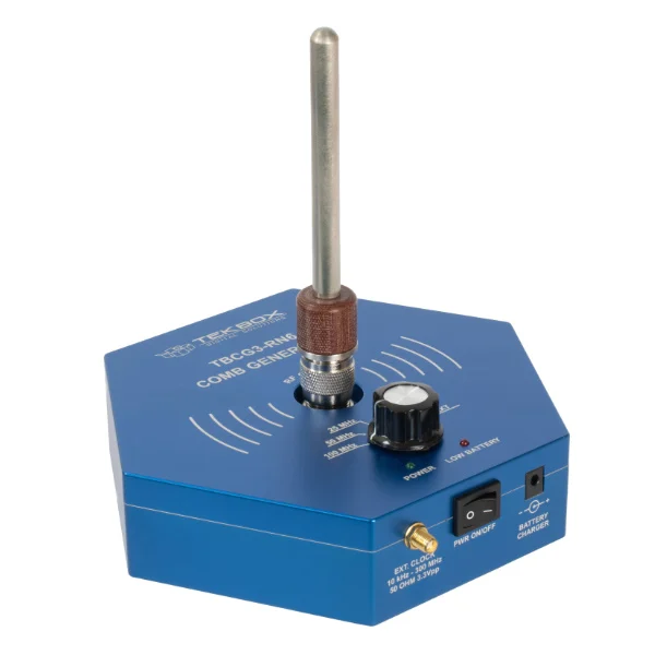
New TBCG3-RN2 Comb Generator Radiated Noise Specified Bandwidth: 5 MHz – 2 GHz Comb Freqencies: 5 MHz, 10 MHz. 25 MHz, 50 MHz, 100 MHz |
New TBCG3-RN6 Comb Generator Radiated Noise Specified Bandwidth: 5 MHz – 6 GHz Comb Freqencies: 5 MHz, 10 MHz. 25 MHz, 50 MHz, 100 MHz |
 |
 |
 |
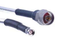
| TBCCx Coaxial Cables N/SMA/BNC/SMB RG 223/U, RG 58/U, RG316/U, RG 142 etc Several Lengths avail. |
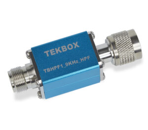
New TBHPF1_9 kHz High Pass Filter, reflective, 50 Ohm 3dB bandwidth: 9 kHz – 3 GHz |
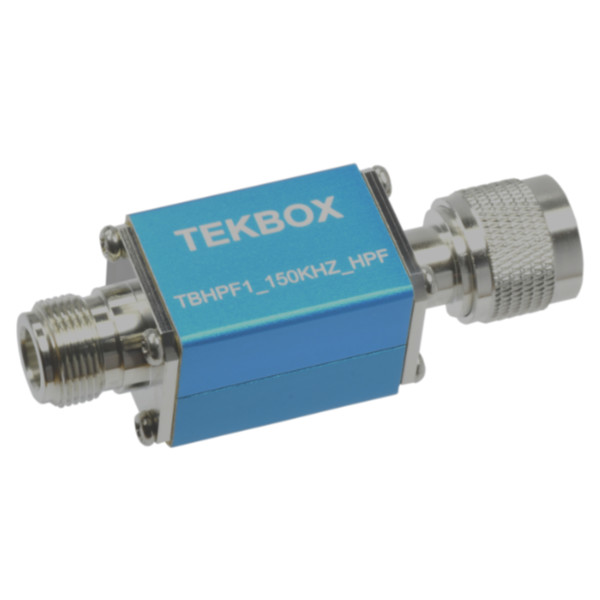
New TBHPF1_150kHz High Pass Filter, reflective, 50 Ohm 3dB bandwidth: 150 kHz – 3 GHz |
 |
 |
 |
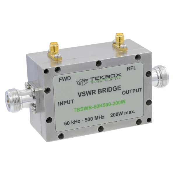
| New TBSWR-60K500 VSWR Bridge/Dual Directional Coupler
|
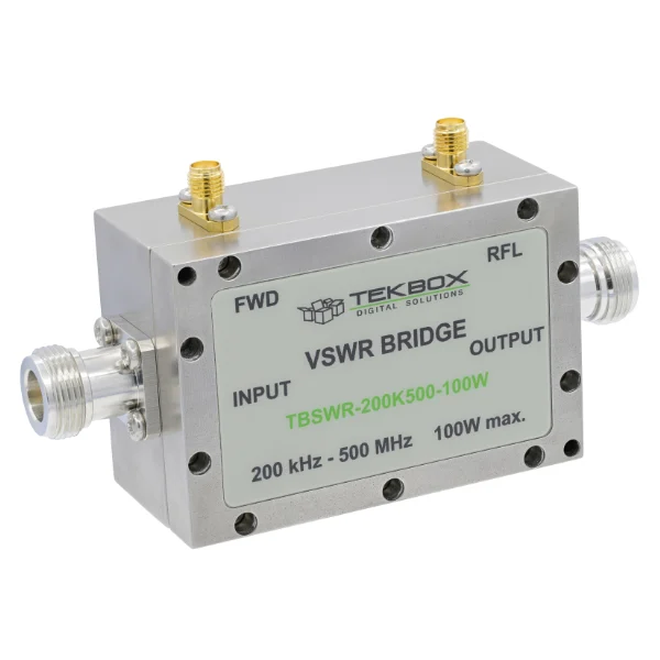
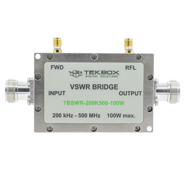
New TBSWR-200K500 VSWR Bridge/Dual Directional Coupler
|
New TBSWR-600K700 VSWR Bridge/Dual Directional Coupler
|
 |
||
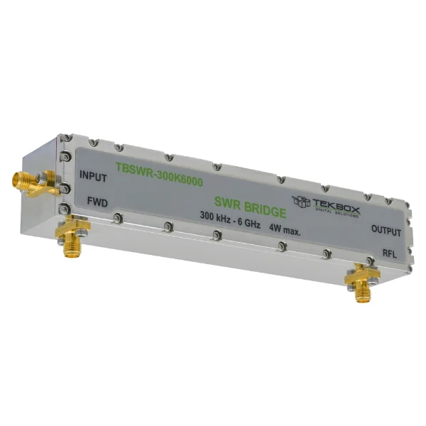
| New TBSWR-300K6000 VSWR Bridge
|
