 |
 |
 |
Fischer Custom Communications, Inc (FCC) designs, develops and manufactures specialized RF test and measurement accessories for EMC testing. These are used for testing electric- and electronic equipment to meet (inter)national regulations for electromagnetic emissions and immunity.
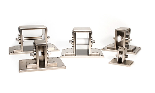
Main products are Current Monitor Probes for conducted EMC measurements acc. IEC/EN61000-4-6. CISPR 22 and CISPR 25, MIL STD 461 and DO160 requirements. Current Injection Probes and Injection Clamps and associated calibration fixtures for conduced immunity testing according to various standards, Coupling Decoupling Networks (CDN’s) for Immunity testing on several ports and many more equipment.
The Fischer Custom Communications equipment is used in various commercial, avionics, aerospace, automotive and military applications.
 |
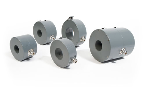
Fischer Custom Communications, Inc. develops and manufactures Bulk Current Injection Probes to meet specific customer and compliance testing requirements. The Bulk Current Injection Probes are used for compliance testing in accordance with several susceptibility specifications. |
| Model | Usable Frequency | Rated Watts CW |
Bandpass insertion Loss/Frequency Range | Aperture (mm) |
| F-120-5 | 10kHz – 100MHz | 100 | <10dB/500kHz – 1MHz | 65 |
| F-120-6A | 10kHz – 400MHz | 100 | <7dB/700kHz – 200MHz | 40 |
| F-120-7B | 10kHz – 400MHz | 125 | <10dB / 1MHz – 400MHz | 65 |
| F-120-8 | 10kHz – 400MHz | 200 | <7dB/800kHz – 300MHz | 40 |
| F-120-8F | 10kHz – 400MHz | 250 | <5dB / 500kHz – 200MHz | 40 |
| F-120-9 | 10kHz – 230MHz | 100 | <11dB/150kHz – 230MHz | 40 |
| F-120-9A | 10kHz – 230MHz | 125 | <8dB/150kHz – 100MHz | 40 |
| F-130-3 | 1MHz – 400MHz | 100 | <7dB/3MHz – 200MHz | 65 |
| F-130A-1 | 1MHz – 400MHz | 100 | <7dB/3MHz – 350MHz | 40 |
| F-140 | 1MHz – 1GHz | 100 | 40 | |
| F-140-HV | 100kHz – 400MHz | 5kV Peak Pulse | <7dB / 2MHz – 300MHz | 40 |
| F-150 | 800MHz – 2.1GHz | 250 | <7dB/950MHz – 2.0GHz | 32 |
| F-150-1 | 2.3GHz – 7.0GHz | 100 | <9dB/2.3GHz – 7GHz | 12 |
| F-150-2 | 800MHz – 2.1GHz | 250 | <9dB / 800MHz – 2.1 GHz | 40 |
| F-070601-1008-1 | 400MHz – 1GHz | 250 | <7dB/450MHz – 1GHz | 40 |
| F-080409-1008-1 | 2.0 GHz – 3GHz | 100 | <9dB / 2GHz – 3.0GHz | 32 |
| F-080728-1008-1 | 500MHz – 1GHz | 250 | <7dB/500MHz – 800MHz | 65 |
| F-080915-1008-1 | 3GHz – 4GHz | 100 | <8dB / 3.2GHz – 3.9GHz | 32 |
| F-120501-1008-1 | 1kHz – 10MHz | 1000 | <9dB / 500kHz – 10MHz | 40 x 91 |
| F-161012-1008-1 | 10kHz – 10MHz | 2500 | <7dB / 200kHz – 10MHz | 54 x 108 |
| F-170501-1008-1 | 10MHz – 400MHz | 2500 | <7dB / 10MHz – 400MHz | 40 |
| F-170701-1008-1 | 10MHz – 400MHz | 1000 | <8dB / 10MHz – 400MHz | 40 |
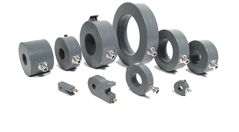 |
The Current Monitoring probes may be used whenever RF current measurements are required. Current measurements are made by placing a current carrying conductor within the “sensing” window of the probe and measuring the probe’s output voltage with an RF detector. Calibration of the probe permits the conversion of the voltages measured to current. Current measurements can be made over the frequency range shown in the transfer impedance curve furnished with each probe. There is virtually no loading of the circuit and the technique permits normal operation of the device under test during measurements. |
![]() Current Probe Calibration Application Note
Current Probe Calibration Application Note
|
Model
|
Frequency Range
|
dBΩ Nom |
ZtΩ Nom |
Connector
|
Aperture | Max Current DC-400Hz |
Max RF Current CW |
| F-110305-1005-1 | 10 kHz – 1 GHz | – | 1 | N | 32 | 100 A | 5 A |
| F-14 | 10 Hz – 500 kHz | -18 | 0.12 | N | 32 mm | 400 A | 5 A |
| F-14A | 10 Hz – 500 kHz | -18.5 | 0.12 | N | 67 mm | 400 A | 25 A |
| F-33-2 | 1 kHz – 250 MHz | Ø | 1 | N | 32 mm | 100 A | 2 A |
| F-35A-L | 100 Hz – 100 MHz | Ø | 1 | N | 32 mm | 200 A | 3 A |
| F-37-2 Clip-on | 100 kHz – 1 GHz | Ø | 1 | SMA | 12 mm | 100 A | 3 A |
| F-38-1 Clip-on | 10 kHz – 200 MHz | 9 | 2.8 | SMA | 5 mm | 20 A | 1 A |
| F-38-2 Clip-on | 1 kHz – 200 MHz | Ø | 1 | SMA | 5 mm | 20 A | 1 A |
| F-38-4 Clip-on | 1 MHz – 1 GHz | 15 | 5.6 | SMA | 5 mm | 20 A | 1 A |
| F-39-1 | 10 kHz – 200 MHz | 9 | 2.8 | SMA | 18 mm | 20 A | 1 A |
| F-39-2 | 1 kHz – 200 MHz | Ø | 1 | SMA | 18 mm | 20 A | 1 A |
| F-39-4 | 1 MHz – 1 GHz | 15 | 5.6 | SMA | 18 mm | 20 A | 1 A |
| F-40-5 | 10 Hz – 50 MHz | -20 | 0.1 | N | 67 mm | 1000 A | 100 A |
| F-42-A | 1 kHz – 100 MHz | 12 | 4 | N | 32 mm | 50 A | 2 A |
| F-52B | 10kHz – 400 MHz | 13 | 4.5 | N | 40 mm | 200 A | 2 A |
| F-57 | 1kHz – 500 MHz | Ø | 1 | N | 40 mm | 200 A | 2 A |
| F-75B | 1kHz – 500 MHz | Ø | 1 | N | 70 mm | 250 A | 2 A |
| F-2000-12mm | 10MHz – 3 GHz | 24 | 16 | SMA | 13 mm | 100 A | 10 A |
| F-2000-32mm-1 | 10 MHz – 2.1 GHz | 22 | 18 | N | 32 mm | 350 A | 3 A |
| F-2000-40mm-1 | 10 MHz – 2.1 GHz | 25 | 18 | N | 40 mm | 350 A | 2 A |
| F-170302-1005-1 | 10 Hz – 50 MHz | -60 | 0.001 | N | 40 mm | 20 A | 2 A |
| F-170308-1005-1 | 10 Hz – 50 MHz | -3 | 0.7 | N | 67 mm | 50 A | 2 A |
| F-170317-1005-1 | 100 kHz – 300 MHz | 11 | 3.5 | N | 305 mm | 1000 A | 2 A |
| F-170329-1005-1 | 10 kHz – 30 MHz | 3 | 1.4 | N | 67 mm | 1000 A | 2 A |
| F-170705-1005-1 | 100 kHz – 30 MHz | 6 | 2 | N | 67 mm | 750 A | 2 A |
| F-170710-1005-1 | 10 kHz – 400 MHz | -9 | 0.35 | N | 32 mm | 50 A | 2 A |
| F-170804-1005-1 | 10 kHz – 400 MHz | 14 | 5 | N | 65 mm | 150 A | 2 A |
| F-180907-1005-1 | 10 kHz – 108 MHz | 15 | 5.6 | N | 127 mm | 500 A | 100 A |
| F-180907-1005-2 | 10 kHz – 108 MHz | Ø | 1 | N | 127 mm | 500 A | 10 A |
| F-180907-1005-3 | 10 Hz – 1 MHz | -20 | 0.1 | N | 127 mm | 1000 A | 10 A |
 |
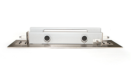
Fischer Custom Communications, Inc. offers clamp-on and fixed-aperture EM Injection Clamps, which offer unique benefits compared to conventional EM Injection Clamps. |
![]() IEC 61000 4-6 Changes in Edition 4
IEC 61000 4-6 Changes in Edition 4
| Model | Aperture | Dimensions LWH | Input Power rating |
| F-203I-A-23mm | 23mm | 610 x 75 x 135 | 10kHz – 1GHz: 100 watts CW (15 min) |
| F-203I-A-32mm | 32mm | 610 x 105 x 190 | 10kHz – 1GHz: 100 watts CW (30 min) |
| DS-F-120615-1006-1 | 22mm | 610 x 64 x 64 | 10kHz – 100MHz: 100 watts CW (30 min) 100MHz – 230MHz: 100 watts CW (15 min) |
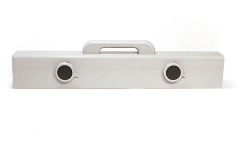 |
CISPR 22, 1197 Amendment #1 2000-08, radiated emissions testing of information technology equipment, requires that all cables leaving the EUT for connection to auxiliary equipment outside the test site shall be filtered with a ferrite decoupling clamp placed on the cables at the point where the cables exit the test site. |
![]() IEC 61000 4-6 Changes in Edition 4
IEC 61000 4-6 Changes in Edition 4
| Model | Apterure mm |
Frequency | Insertion Loss | Length mm |
With mm |
| F-203I-A-DCN-23mm | 23 | 100 kHz – 100 MHz | See Data Sheet | 610 | 75 |
| F-203I-A-DCN-32mm | 32 | 100 kHz – 100 MHz | See Data Sheet | 600 | 95 |
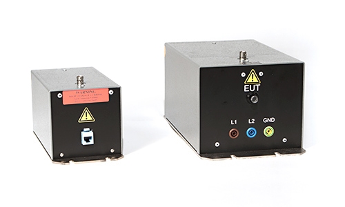 |
The common mode current disturbance signal can be delivered to the EUT using a variety of coupling networks to inject the signal onto the unscreened cables, shielded cables, balanced cables, coaxial cables and power mains. Decoupling networks are used to insure that the disturbance signal does not influence the auxiliary equipment and are placed between the EUT and the auxiliary equipment. |
