
In the past two months, Teledyne LeCroy has launched several technical resources on EMC / EMI measurements with real-time oscilloscopes.
Free on-demand webinars by Signal Integrity Evangelist Dr. Eric Bogatin
Recently, Teledyne LeCroy has published a two-part webinar series about how real-time oscilloscopes and near field probes can be used in pre-compliance EMC Testing. In these webinars Dr. Eric Bogatin, known for years as signal evangelist, demonstrates how to transform time domain information into real time spectrum in the frequency domain.
Test Happens BLOG
For more information on EMC testing with oscilloscopes, we also recomment reading recently added articles in Teledyne LeCroys Test Happens BLOG.

There are three, principal root causes of the common currents that lead to radiated emissions in electronic devices:
- Return path discontinuities
- Physical structures that are not tightly coupled to the return plane
- Ground loops causing common currents in cables
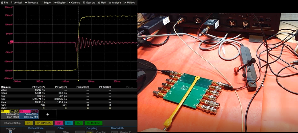
We’ll briefly demonstrate a bench top test for finding sources of near field radiated emissions caused by return path discontinuities using a real-time oscilloscope in the time domain.
Why the time domain? Although EMC compliance testing is done in the frequency domain, in the time domain we can see the signatures of near field emissions in a way that yields information about the root causes of those emissions. It is a type of pre-compliance EMC testing that can be easily done in your lab, without the expense of an anechoic chamber.

When we are testing a product on our bench top for EMC, we are in close vicinity to that product in a typically noisy environment. All we can measure is the near field, the electric or magnetic field strength in close proximity to our product. It’s important to keep in mind that near field measurements are not the same as the far field (3 m or more) measurements in the FCC Part 15 Radiated Emissions test described earlier, and here’s why.

In our last post, we discussed how little radiated emissions it takes for an electronic product to fail an FCC certification test for EMC.
Where do these radiated emissions come from? No one designing an electric circuit board is designing them into their product on purpose. These sneaky antennas do not appear in the schematic. However, we can unwittingly introduce them into our product through certain styles of board and interconnect design features. It is sometimes jokingly said there are two kinds of designers: those who are designing antennas on purpose, and those who aren’t doing it on purpose. We’re going to introduce two, basic models of antenna—magnetic dipole and electric dipole (Figure 1)—to reveal a secret source of radiated emissions.

When designing an electric circuit board, we always start with a schematic. All it tells us is the components in use, how they are connected, and what the functionality of the system is. The schematic tells us absolutely nothing about signal integrity, power integrity or electromagnetic interference (EMI). All the schematic tells us about is the connectivity.
Problems with signal integrity, power integrity and EMI all come to life when we turn that schematic into a physical implementation, because once we have connectivity established by the interconnects, the only thing interconnects are going to do is screw up our beautiful design. They’re going introduce noise, and that noise is going to cause some combination of signal integrity, power integrity and EMI problems. The best we can do is to minimize its appearance and impact using best design practices.
In this series, we’ll focus on design issues that affect EMI, and how you can use a real-time oscilloscope to find the root causes of EMI that negatively affect a product’s electromagnetic compatibility (EMC).